DMK

The DMK is a compact and powerful measurement solution designed for inverter-driven motors.
It precisely measures phase currents and PWM-voltages and perfectly synchronizes them to the rotor position, providing real-time visualization and data storage.
With its integrated functionalities, DMK simplifies motor analysis, making it an essential tool for development, benchmarking and endurance tests.
Beyond its core capabilities, the DMK replaces multiple laboratory instruments. This not only saves cost and space but also delivers measurement results specifically tailored to motor control applications, making it an all-in-one solution for engineers.

The Usage of DMK

Power Electronic Testing

the unique PWM decoding for high-frequency, high-resolution signals beyond typical instrument capabilities. Its advanced voltage measurement decodes PWM in real time, revealing the exact inverter voltages as the motor experiences them. Without common filtering, any inverter malfunction is easily detected rather than masked.

Development Engineers in Motor Control

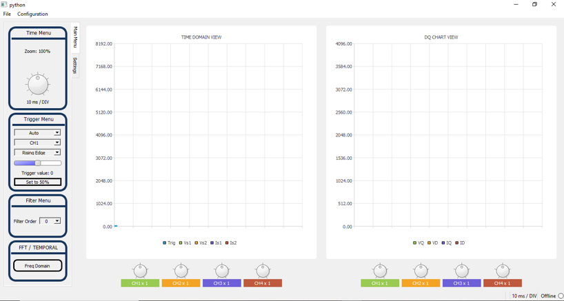
As a compact, multifunctional measurement instrument that replaces multiple separate devices.They connect DMK to their motor/inverter system to gather analog signals and key motor-control variables for scope and visualize in real time with the DMK PC-Software
Access internal state variables of both the motor and the inverter directly.
Record and store data for extended analysis and documentation

Long-Time Tests

Measure and log all motor and inverter state variables over an extended period.
Identify anomalies or performance degradation that might occur only after hours, days, or weeks of continuous operation.
Automated data analysis on the extensive datasets provided by the DMK helps uncover hidden or statistically rare problems that are difficult for humans to detect”

Benchmarking Reverse Engineering

Analyze third-party or competitor drive systems with minimal setup, tapping directly into motor and inverter signals. DMK gathers precise data for fair performance comparisons—efficiency, accuracy, control strategy—and provides actionable insights to optimize designs, inform purchases, and guide partnerships.

HMI

Visualisation Interface

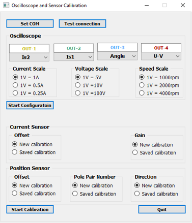
Configuration Interface

Spécifications

Tableau de Spécifications
Default configuration Possible configuration
Power Supply USBC 3Amp
Battery 4000Ah
Input From Inverter (3 Phases)
Output To Motor (3Phases)
Maximum Current (Inverter) 15 Amp 1 Amp – 200Amp
Max Votage (Phase to Phase Inverter) 400V Peak 40V-400V Peak
PWM Frequency Max 20kHz 4-40kHz
Encoder type Incremental A,B,Z Incremental (ABZ), SPI, …
Isolation 600V 600V